
Troubleshooting Dieline Import in PackCAD Mockup
PackCAD Mockup is an online tool that validates the 3D structure of your packaging designs and creates realistic 3D product mockups before you ever build a physical prototype. PackCAD’s built-in Dieline Inspector helps catch issues in the geometry of your dieline so you can correct them prior to import. This guide walks through the most common dieline issues our customers encounter and how to fix them.
Dieline Inspector
When you import a dieline, the Dieline Inspector opens automatically and walks you through the import workflow. It flags anything worth a second look and lets you inspect each issue directly. Click Continue to advance through the Dieline Inspector steps, and Finish to import the dieline into your project for folding.
Common Dieline Issues
Most dieline import problems come down to small details that are quick to fix in a vector editor (e.g. Adobe Illustrator, Inkscape, CorelDRAW). The Dieline Inspector sorts what it finds into errors and warnings: errors must be fixed before you can import, while warnings let you continue but are worth understanding first.
Invalid Stroke Colors
The most frequent reason a dieline fails to import is because its lines are drawn in the wrong color. PackCAD Mockup uses the stroke color of each line to tell cuts from creases, so each line needs to use one of the accepted colors below.
- Cut lines should be black (#000000) .
- Crease (fold) lines should be red (#ff0000) , blue (#0000ff) , magenta (#ff00ff) , or yellow (#ffff00) .
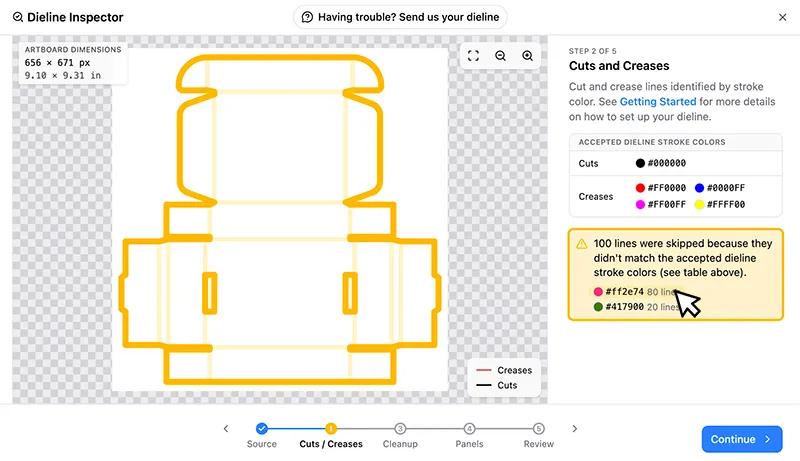
If the Dieline Inspector reports lines were skipped because they didn’t match the accepted dieline stroke colors, your lines are using a color PackCAD Mockup doesn’t recognize. Lines in invalid colors are skipped, and lines with no stroke at all are also skipped. The warning will give a list of the ignored colors used in your dieline, and you can hover over each one to see the affected lines highlighted. Recolor your dieline to match the accepted colors, then re-import. See Prepare Dieline for more details.
Artwork in Dieline
Your dieline file should contain only the cut and crease lines for the design you’re folding. Leave printed artwork, dimension labels, logos, and registration marks out of the dieline, and import artwork separately once the dieline is loaded.
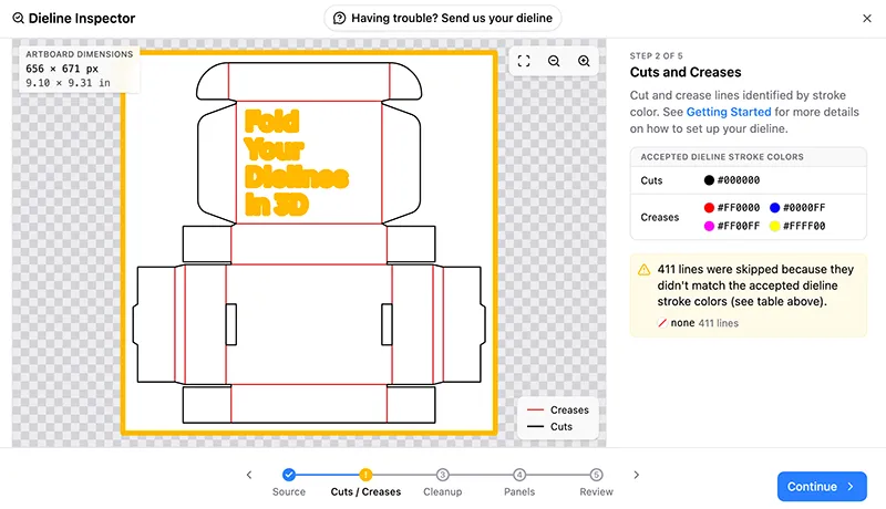
Anything that isn’t a cut or crease line — extra shapes, text, logos, and labels — is skipped during import and listed in the Dieline Inspector, so you can see exactly what was removed. You may see the following warnings: lines were skipped because they didn’t match the accepted dieline stroke colors and unsupported SVG elements were skipped. Omitting these items from your dieline keeps the import clean, avoids surprises, and speeds up the import process. See Prepare Dieline for more details.
Gaps
The Dieline Inspector flags cut or crease endpoints that are almost touching but not actually connected to nearby geometry, reported as sets of points are almost touching but not connected. Small gaps like these are common; they look connected when zoomed out or using a thick stroke width, but unintentional gaps should be corrected in a vector editor and re-imported into PackCAD Mockup.
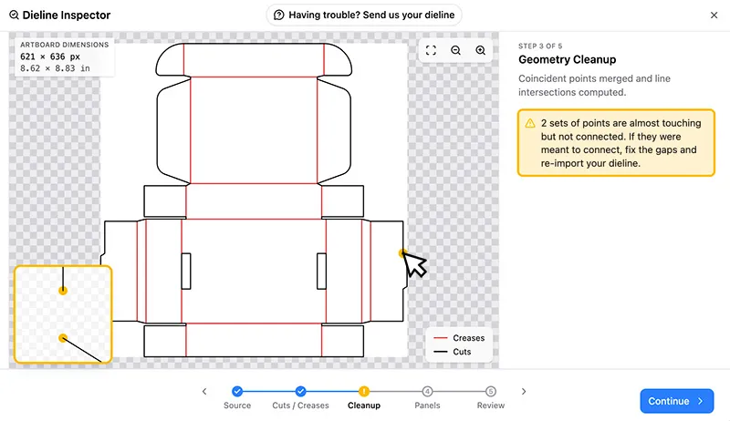
Sometimes, PackCAD Mockup may flag an area where there is an intentional small gap that’s just part of your design; it’s OK to ignore those cases and hit Continue. Hover over the warning indicator on the dieline to see a magnified view of the issue in the bottom left corner of the Dieline Inspector in order to determine whether a correction is needed.
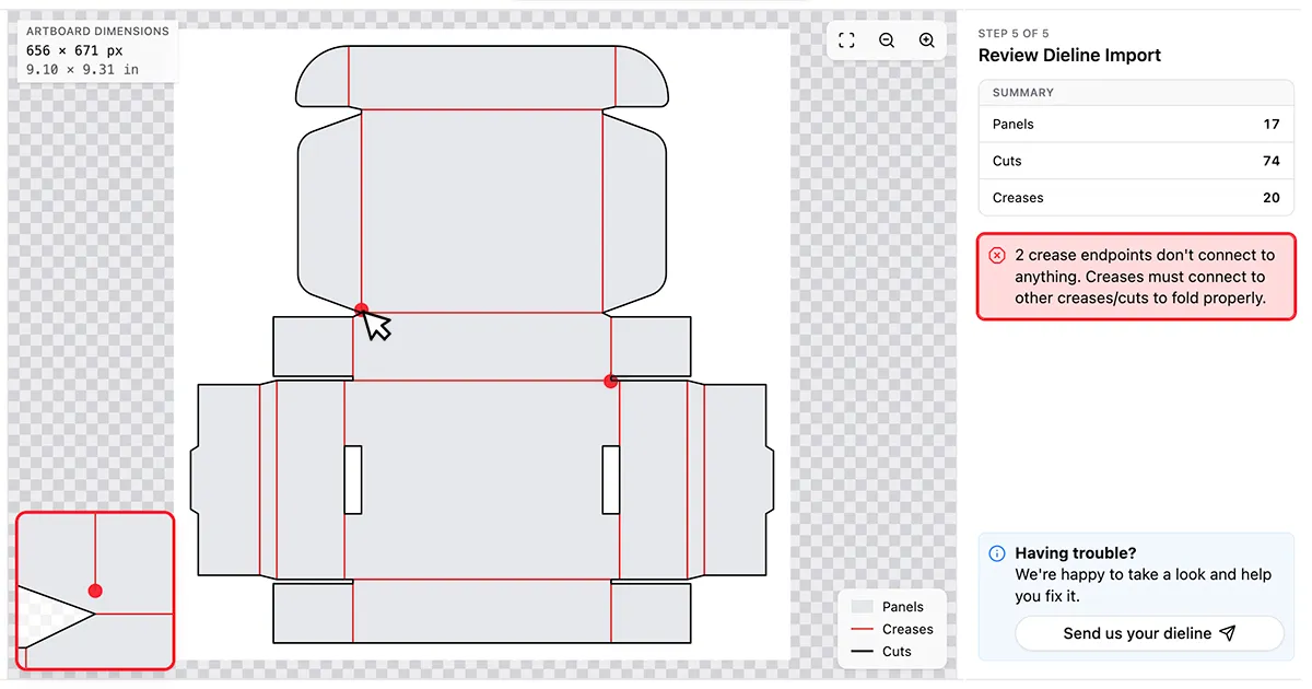
A crease endpoint that doesn’t connect to the rest of the dieline is reported as crease endpoints don’t connect to anything, an error you must fix before importing (see below). Every crease needs to meet another crease or a cut at both ends in order to fold properly.
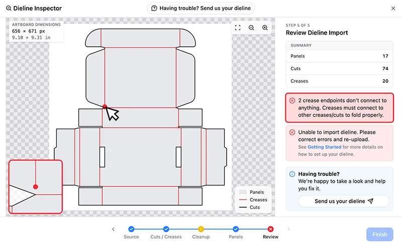
Dashed Lines
Crease lines are often drawn dashed in dieline drawings, but each crease needs to be a single continuous line for PackCAD Mockup to parse it correctly. If a dashed line is drawn as a row of separate dash segments, PackCAD Mockup reads each segment as its own short, disconnected crease instead of a single, continuous crease. These disconnected segments may generate a crease endpoints don’t connect to anything error (see Gaps) because they don’t connect to the rest of the dieline.
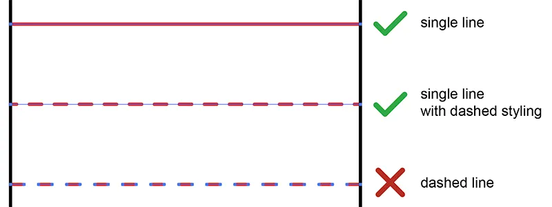
If you encounter this error, try removing any dashed styling from your crease lines and see if the creases have been constructed from several segments rather than a single line. If needed, draw each crease as a single continuous line, then re-import.
T and L Junctions
A T-junction is three creases meeting at one point, and an L-junction is two creases meeting at one point in the middle of the dieline (not near a cut edge). Both can keep a design from folding cleanly, so the Dieline Inspector flags them as warnings: T-junctions found (three creases meeting at a single point) and L-junctions found (two creases meeting at a single point).
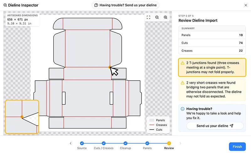
Often T and L junctions are created because there is some slight misalignment in how the dieline was drawn, so verify that your creases are positioned correctly and fix any Gaps if needed. In the example above, the horizontal crease was drawn slightly higher than it should have been, resulting in both a T-junction warning and a Short Crease warning. If a T or L junction is intentional, you can Continue, but check that the design folds the way you expect.
Short Crease
The Dieline Inspector flags very short creases that are the only thing bridging two panels that do not share any other common creases, reported as very short creases were found bridging two panels that are otherwise disconnected.
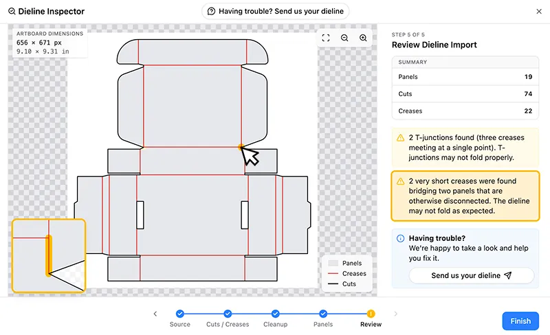
A bridge this small is often unintentional and due to a slight misalignment in the dieline (you may also see T-junction or Gap warnings alongside the short crease warnings as is the case in the example above). If it was unintentional, it should be corrected in a vector editor and re-imported as it can cause problems with folding. One way to correct this issue is to convert the short crease line into a cut line.
Overlapping Lines
The Dieline Inspector flags lines that sit directly on top of one another but carry conflicting roles (for example a crease line drawn over a cut line) and reports overlapping line pairs were found with conflicting assignments. When this occurs, PackCAD Mockup can’t tell which line assignment you meant, and will pick one for you — which may or may not align with your intention.
To fix this warning, delete the duplicate in a vector editor, or recolor the lines so the overlap has a single, consistent assignment, then re-import.
Short Lines Removed
The Dieline Inspector automatically removes very short line segments (less than 0.5px long) and reports very short lines detected and removed so you can see what changed. These are usually stray fragments left behind when the dieline was drawn, and removing them rarely affects how the dieline folds, but you can correct them and re-import to remove the warning.
Stray Lines Removed
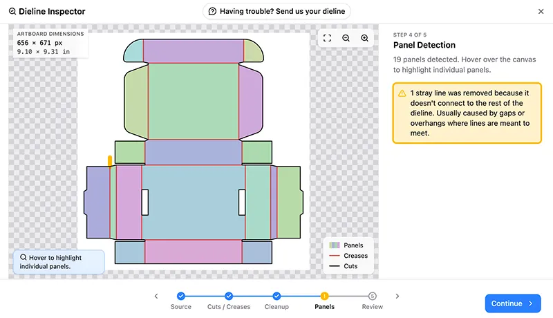
Lines that are found not to be adjacent to any identified panels (the regions between creases) are removed automatically and reported in the Dieline Inspector as stray lines were removed because they don’t connect to the rest of the dieline. This is usually caused by an overhang where a line extends past the point it should connect to. Overhang issues can generally be ignored:
Sometimes if there is an unintentional gap in the perimeter of the dieline, it can prevent a panel from being identified. This may result in a missing panel and many lines being removed from the dieline:
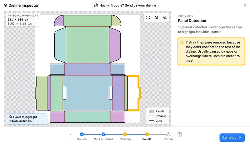
In these cases, check the dieline for any gaps in the geometry, fix in a vector editor, and re-import until you see the warning disappear.
Still Stuck?
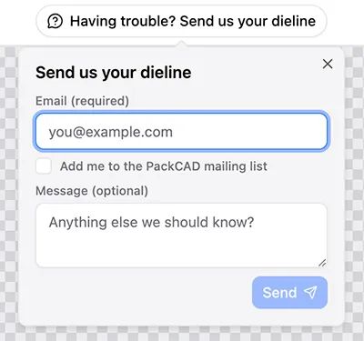
If something doesn’t look right and you’re not sure why, click Send us your dieline at the top of the Dieline Inspector to share the file with the PackCAD team for help:
Once your dieline imports cleanly, see Getting Started to learn how to apply artwork and fold your design into a 3D mockup.