Photorealistic 3D Packaging Visualizations with PackCAD Mockup and Blender
PackCAD Mockup is an online tool that folds flat dielines and print graphics into a realistic 3D packaging mockup. This guide walks you through folding your 2D design into 3D with PackCAD Mockup, exporting a 3D model, and creating a photorealistic product rendering using the free, open-source Blender software.
Prepare 3D Model
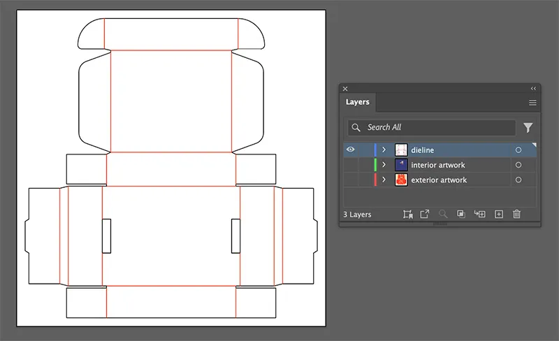
Using PackCAD Mockup, generate a 3D model of your packaging design, and export it as a .glb file. Our Getting Started guide explains the process of folding a 2D dieline (the cut-and-fold pattern for your box) into a 3D model. All you need is a 2D design file, such as one created in Adobe Illustrator:
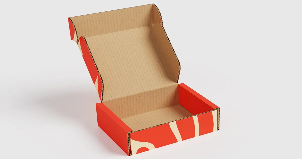
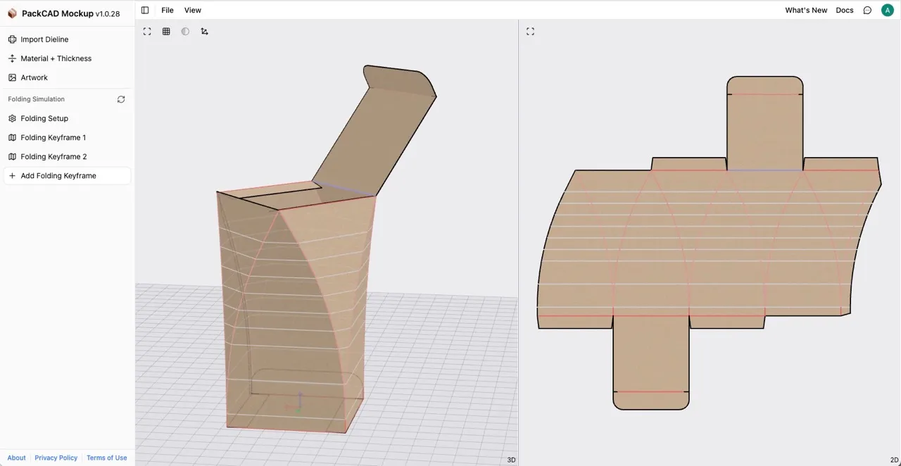
PackCAD Mockup runs directly in your web browser and is free to try. It includes a set of material presets, including common paperboard and corrugated options. After uploading your dieline and artwork, you can select a material and begin folding your model in 3D. In the example shown below, a mailer box made from E-flute corrugated cardboard is folded and posed in 3D, with artwork applied to its exterior panels.

Blender Template
Once you’ve generated a .glb file from PackCAD Mockup, you can import it into our Blender template for rendering. Blender is a free, open-source 3D tool used to create high-quality, photorealistic renderings and animations. Download Blender here (this tutorial uses Blender 5.0).
Download our PackCAD Mockup + Blender template PackCAD_Blender_Template.blend to follow along.
Setup and UI
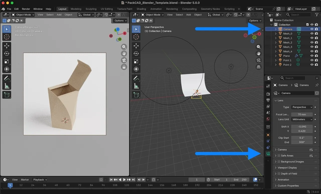
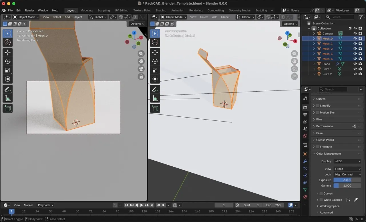
When you open the Blender template, an example packaging model is loaded in the 3D viewer. As shown in the image below, the main screen is split into two views: the Camera Perspective on the left and the full 3D scene (the User Perspective) on the right.
The Camera Perspective shows what Blender will render, with the bounds of the rendering shown in the rectangle at the center of the view. First, switch the Viewport Shading mode to Rendered to preview the rendering in full color. To do this, drag the center divider to the right, then select Viewport Shading: Rendered from the upper-right corner of the Camera Perspective view.
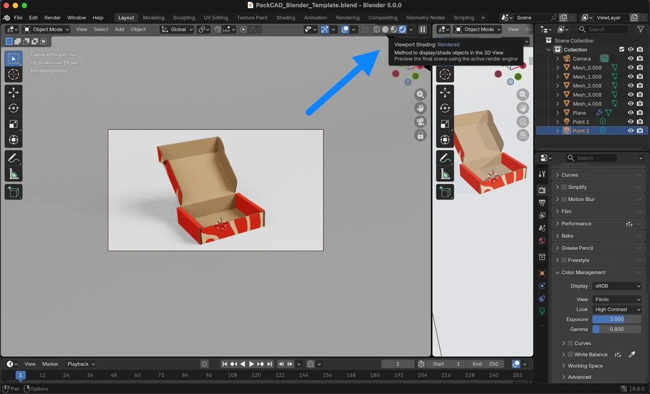
This Blender template includes a basic studio lighting scene, which is ideal for product rendering. You can navigate around the 3D scene using the right viewport (the User Perspective). In the 3D scene, you will find our packaging 3D model, a camera, two point lights, and a curved, white backdrop.
The elements of our scene are listed under Scene Collection in the upper-right corner of the Blender interface. Our sample model is split into five meshes, labeled Mesh_0–Mesh_4. Each mesh represents a different surface of the model (interior, exterior, edge profile, etc.). Click through each mesh in the menu to see it highlighted in the 3D view.

Test Render
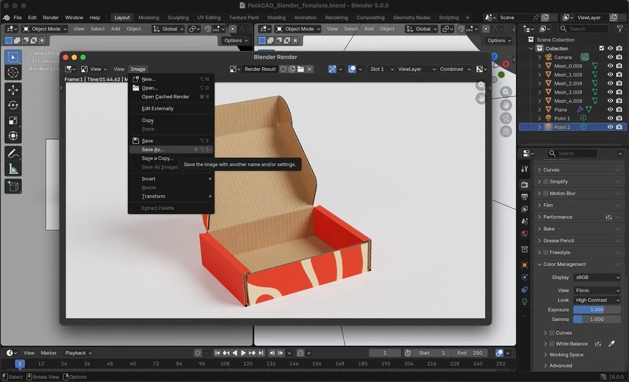
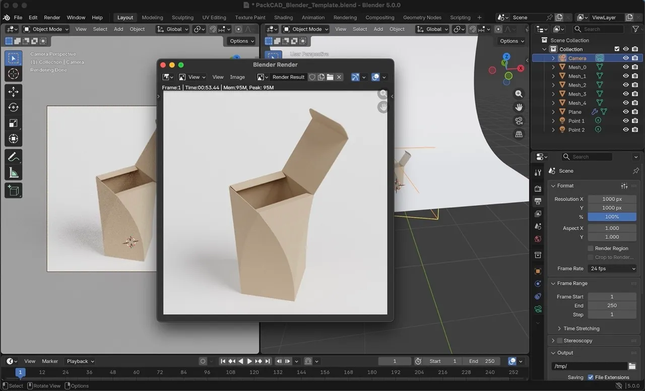
Now you can create a test render of the current scene. In the upper-left corner of the screen, select Render > Render Image. This will open a new window where your image will begin processing.

Rendering may take anywhere from a few seconds to several minutes, depending on your computer’s hardware configuration. When finished, save the image by selecting Image > Save As.
Remove Meshes
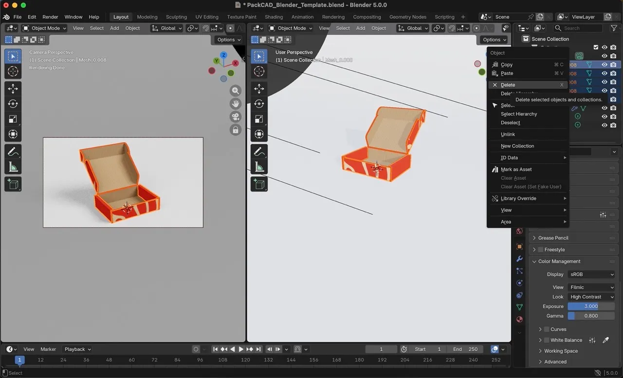
Finally, remove the sample model by selecting all five Mesh objects in the upper-right menu, right-clicking, and selecting Delete. Now you are ready to import your own design into the Blender template.
Import Your Design
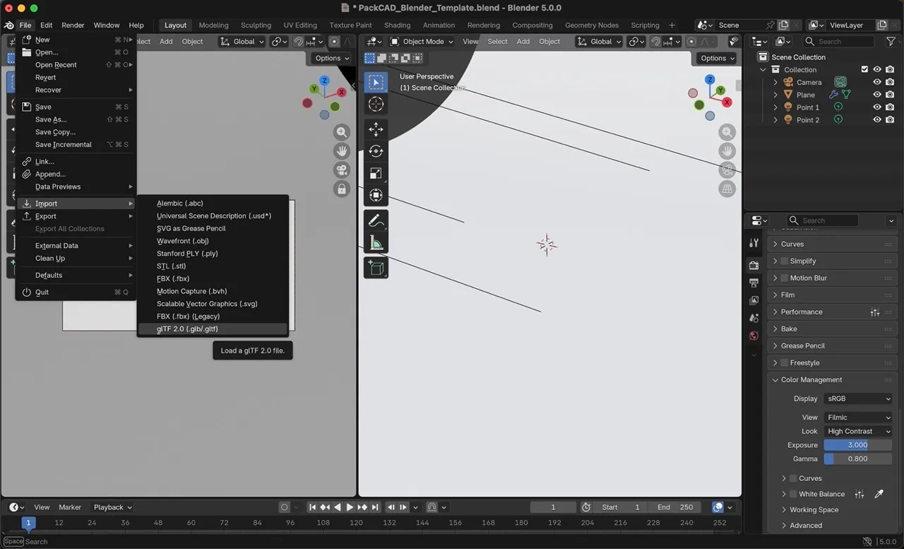
Import your .glb file using File > Import > glTF 2.0 (.glb/.gltf).
In the following steps, we’ll use curved_box.glb , a curved packaging design folded in PackCAD Mockup, as our working example.
Adjust Camera Settings
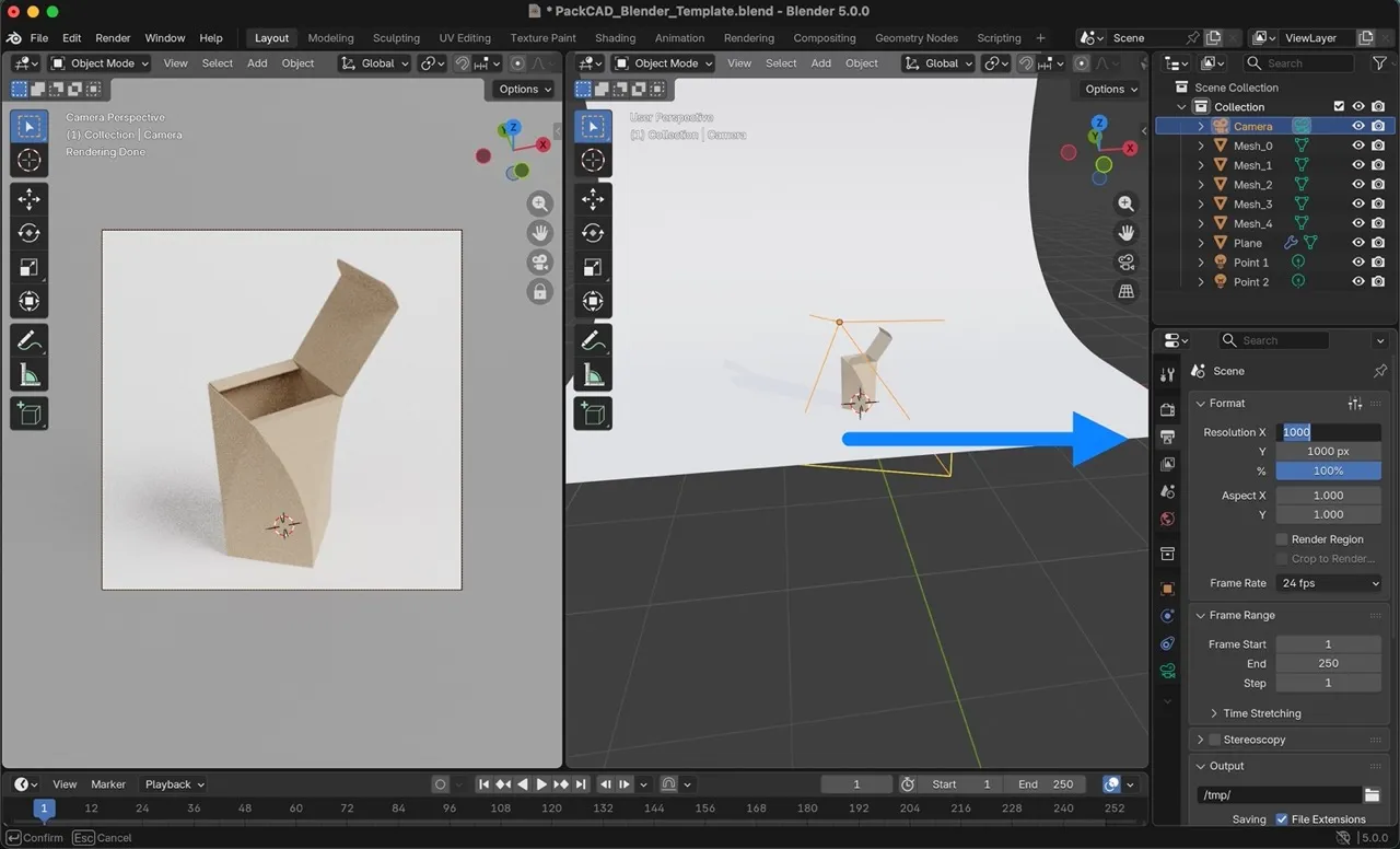
If you set the units for your dieline in PackCAD Mockup, your 3D packaging mesh should import at the correct scale in Blender. Depending on the size of your packaging, you may need to adjust Blender’s camera settings to fit your model within the render frame.
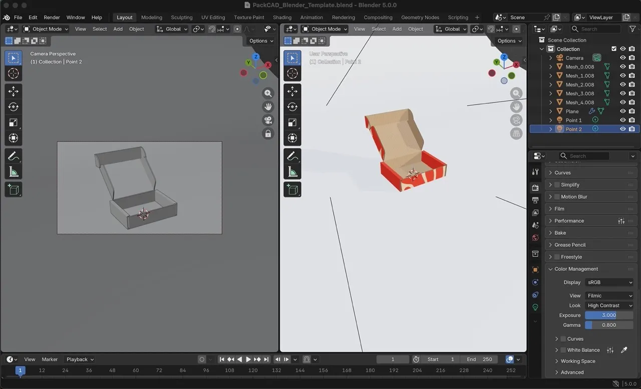
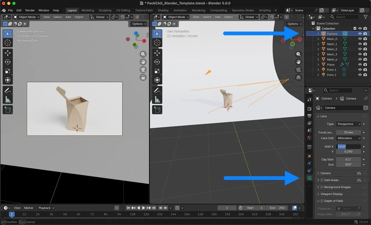
Our curved box model is approximately 13” tall, and as you can see in the image below, it does not fit within the viewport of our current rendering setup (left window in the image below).
In the Camera Perspective view (left window), scroll to adjust the camera’s distance from your model, and right-click and drag to change the angle until you are happy with the composition.
If your packaging is not centered in the Camera Perspective frame, you can adjust this by selecting the Camera in the upper-right menu, then selecting the camera icon in the lower-right menu and adjusting the Shift X/Y parameters.
Rotate Model
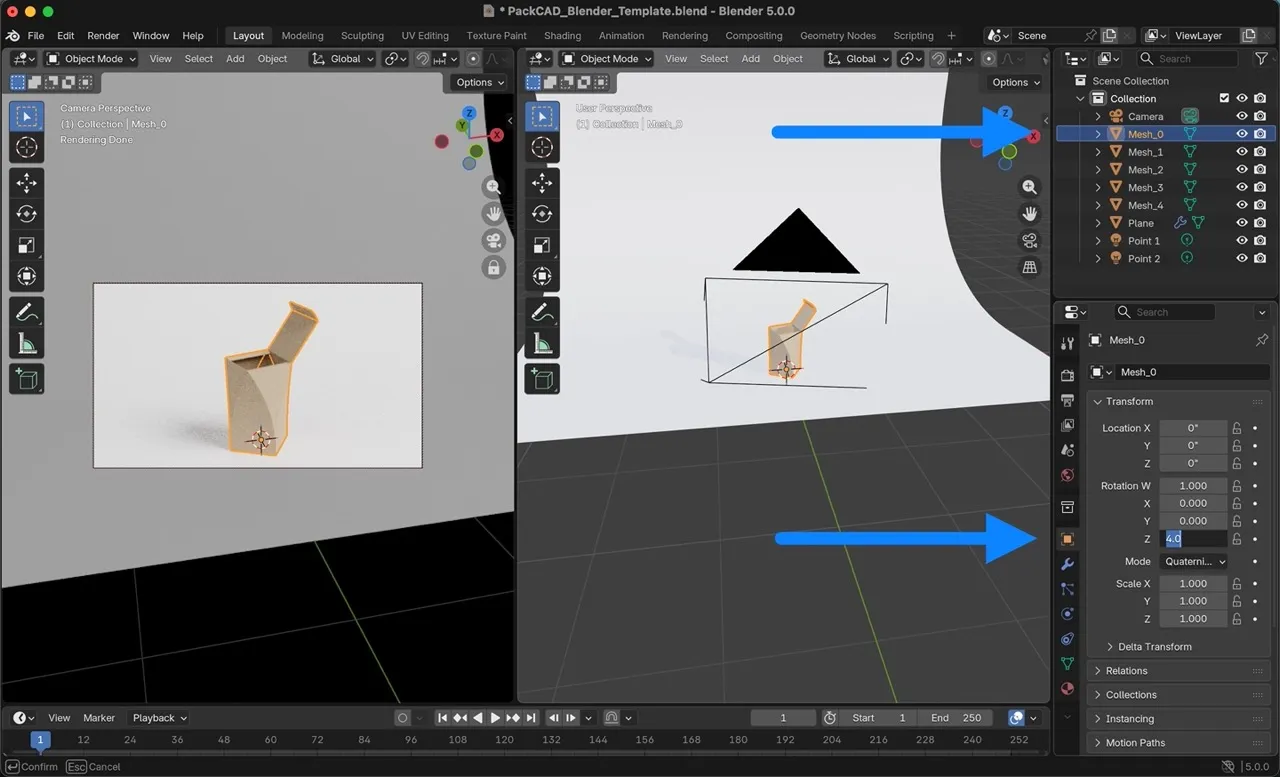
You may also want to rotate the model to achieve a better overall composition. To do this, select each mesh in the upper-right menu, then select Object Properties in the lower-right menu, and set the mesh’s Rotation. Be sure to set the same rotation for all five meshes in your scene. In our case, we rotated each mesh by 4 radians around the Z-axis.
Render
You can adjust the aspect ratio and resolution of your rendering by clicking on Output Properties in the lower-right menu. Resolution X and Y determine the final dimensions of your rendering; we set the resolution to 1000px x 1000px for this example.
Once you have everything set up, select Render > Render Image to create your final rendered image.
Postprocessing
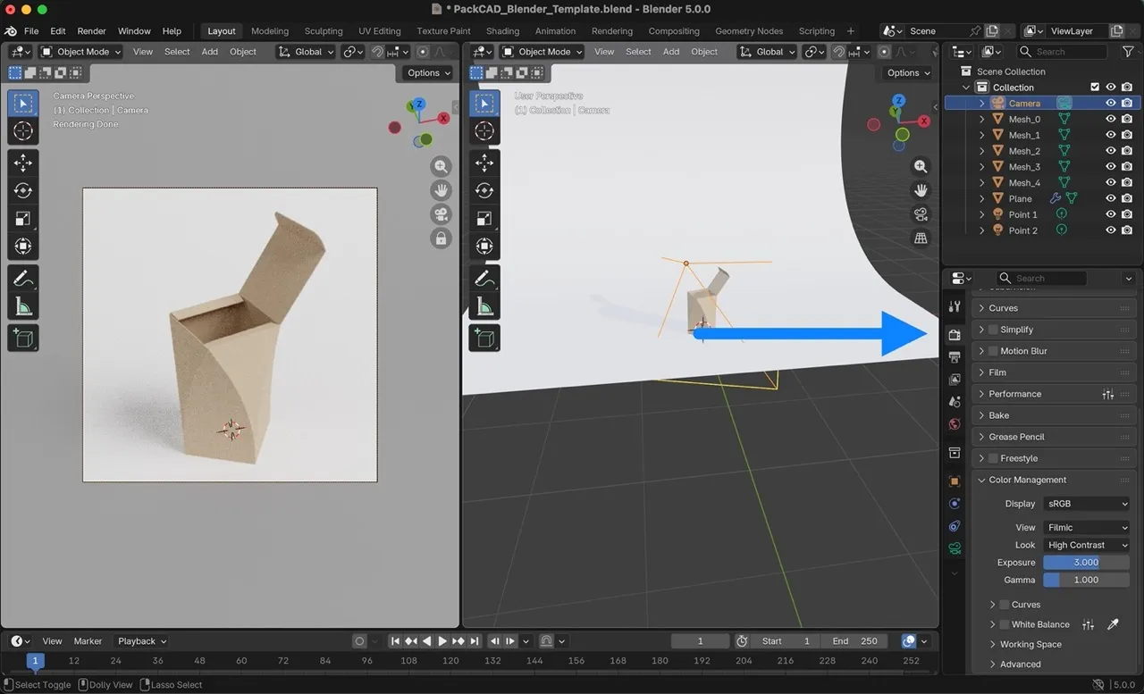
Once rendering is complete, you can apply additional post-processing (such as brightness, contrast, and color correction) using an image editor of your choice. In our experience, these final global adjustments are often best handled outside Blender.
Additional Settings
At this point, you have completed the core rendering workflow. This section covers additional Blender settings that can be adjusted to further customize your rendering.
Adjusting Lighting and Exposure
Our Blender template contains two point lights. You can adjust them by selecting a point light in the upper-right menu and then clicking the lightbulb icon in the lower-right menu. Power sets the strength of the light and Radius sets the hardness of the light/shadows (smaller radius = harder light). Point 1 is a brighter and slightly harder light that casts the main shadows in the scene. Point 2 is a softer fill light that helps to lighten some regions that were not covered by Point 1. The backdrop also reflects both lights and helps soften the overall appearance.
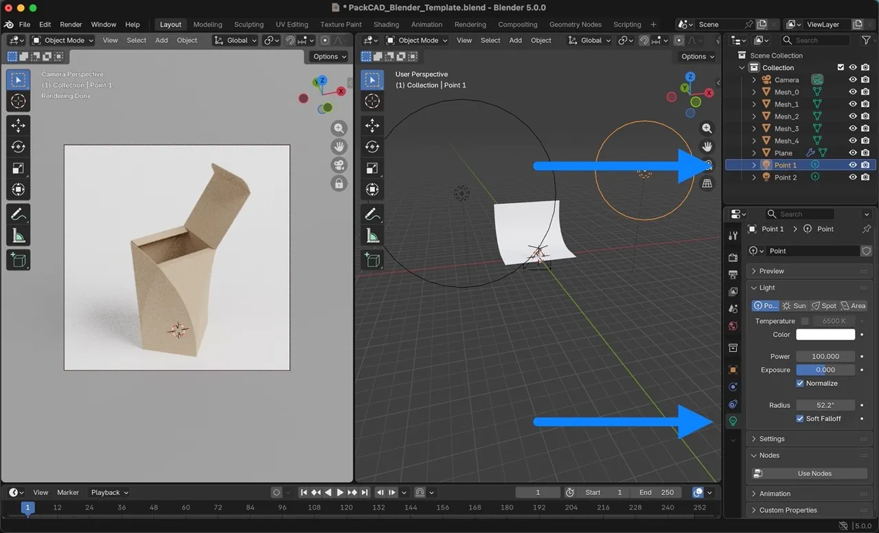
You can also adjust the position of the lights in the scene, either by clicking into Object Properties in the lower-right menu, or by selecting the light in the upper-right menu and pressing G to put Blender into Move mode. While in Move mode, you can press X, Y, or Z to constrain movement along an axis.
G to grab and move any object, then X, Y, or Z to constrain movement to a single axis. Additionally, you can click on Render Properties in the lower-right menu and adjust the overall Exposure of your rendering.
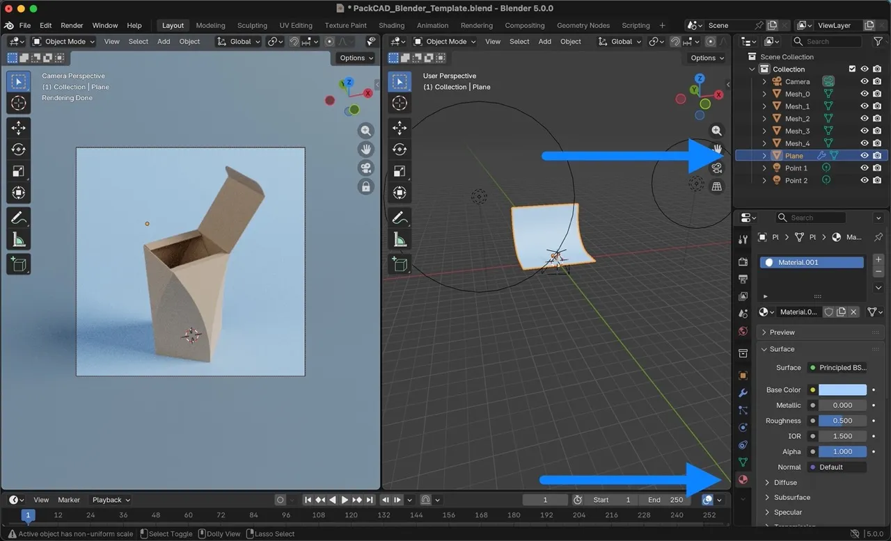
Background Color
Adjust the background color by selecting the Plane object in the upper-right menu, then selecting Material Properties from the lower-right menu and changing the Base Color.
Focal Length
The focal length sets the amount of perspective distortion in your rendering, with small focal lengths giving a more fisheye appearance, and large focal lengths making lines appear more parallel. 50mm is considered a neutral focal length that is similar to the human eye, though the focal length you use is up to your preference. Our Blender template uses a Perspective camera with a focal length of 70mm. If you prefer the look of a longer focal length, you might also try using an Orthographic camera, which is essentially a focal length of infinity (no perspective distortion).
To change the camera settings, select the Camera in the upper-right menu, then select the camera icon in the lower-right menu. From there, you can set the camera type and focal length.