PackCAD Mockup Tips and Tricks
PackCAD Mockup is an online tool that converts flat dielines into realistic 3D packaging mockups. This guide covers tips and tricks for getting the most out of the software. We’ll be adding more to this guide throughout 2026, so please check back for updates.
User Interface Shortcuts
Drag and Drop
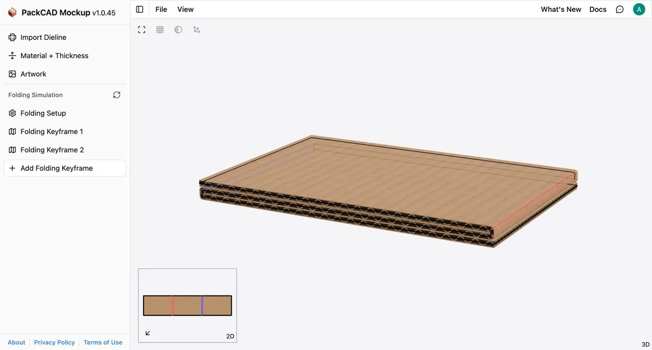
At any time, you can drag a dieline (SVG) or project file (JSON) into PackCAD Mockup to open it as a new project:
Similarly, you can drag artwork (PNG/JPG) into your design at any time. It will be applied to the exterior or interior of your design, depending on which slot is available:
Hotkeys
2- Toggle to dieline view layout (2D).3- Toggle to folded model view layout (3D).R- Replay keyframe when editing a folding keyframe, or replay folding simulation if no keyframes or other operations are currently selected.Ctrl/Command + A- Select all creases in your design when editing a folding keyframe:
Ctrl/Command + S- Save your project as a JSON file.
If you have ideas for additional hotkeys that would save you time, please let us know at support@formfinding.studio.
Preferences
Click in the header to open the Preferences menu. Here you can customize defaults for view layout, units, material and thickness, camera, and more. These defaults are saved and restored each time you open the app — settings changed elsewhere in the app are temporary and will reset on your next visit.
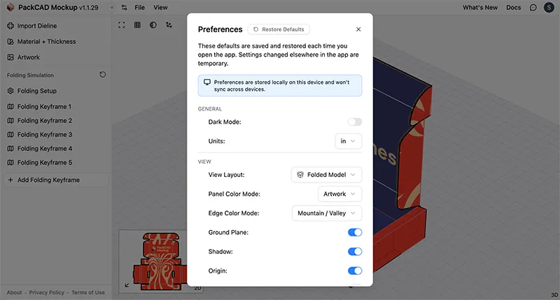
Preferences are stored locally on your device and won’t sync across other devices or browsers. To reset everything back to defaults, click the Restore Defaults button at the top of the Preferences menu. See our User Interface guide for a detailed breakdown of preferences.
Number Input
Select the fold angle input and scroll to adjust the angle incrementally. You can also use the Up/Down arrow keys:
Fixing Overlapping Panels
Sometimes you may notice that two or more panels of your design overlap in 3D, creating visual glitches in the overlapping region. This is caused by the panels lying in exactly the same plane in 3D space:
In the long term, we plan to introduce an interface in PackCAD Mockup that will allow you to specify which panels are on top and which are below, but until that is ready we recommend making some small adjustments to your dieline or fold angles in order to offset panels slightly in 3D. In the following sections, we’ll walk through some simple examples.
These fixes are only for visualization purposes and are not intended to reflect manufacturing requirements; actual production details should be confirmed with your manufacturer.
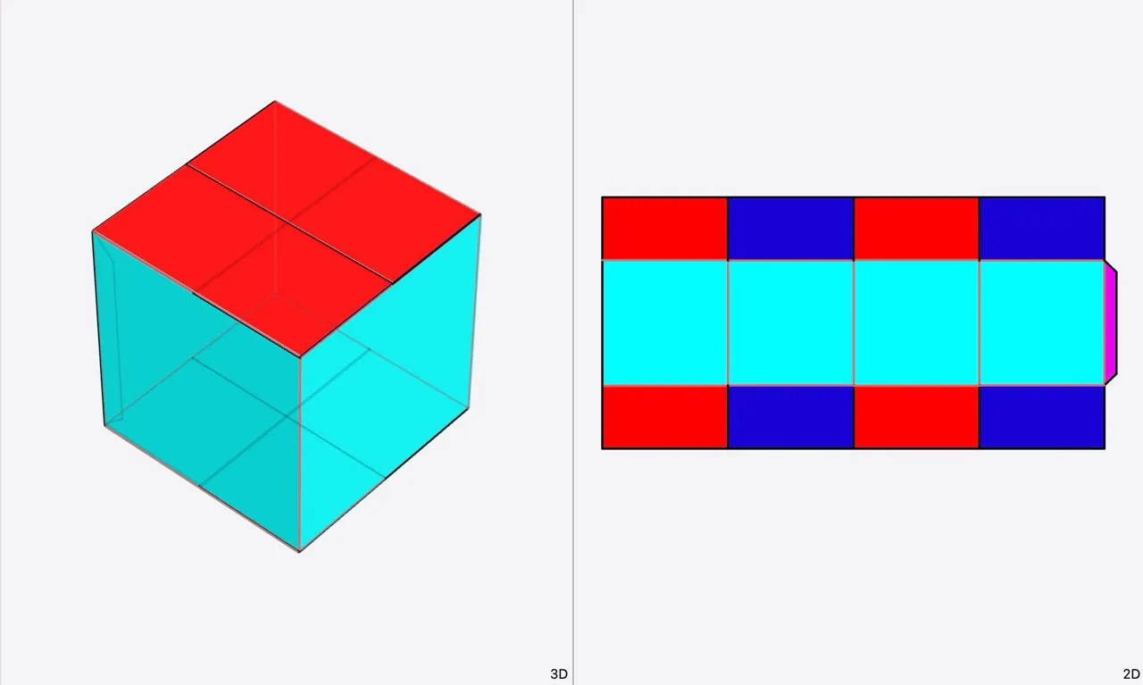
In this first example, we have a box with the red and blue closure flaps on the top and bottom of the dieline lying in the same plane in 3D. Additionally, we can see that the magenta glue flap is lying in the same plane as the side of the box, colored in cyan.
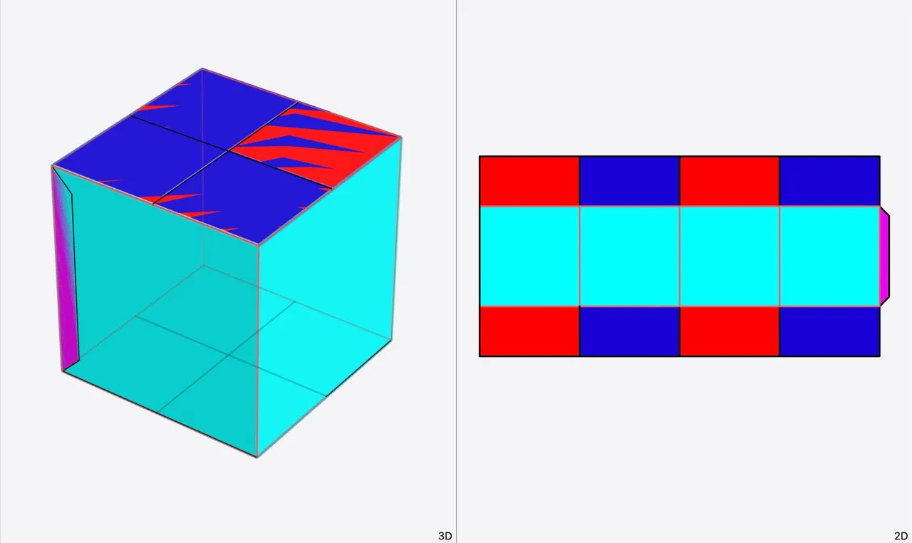
In order to fix this design, we want the blue flaps to lie below the red flaps and the glue flap on the inside of the box.
Angle Adjustment
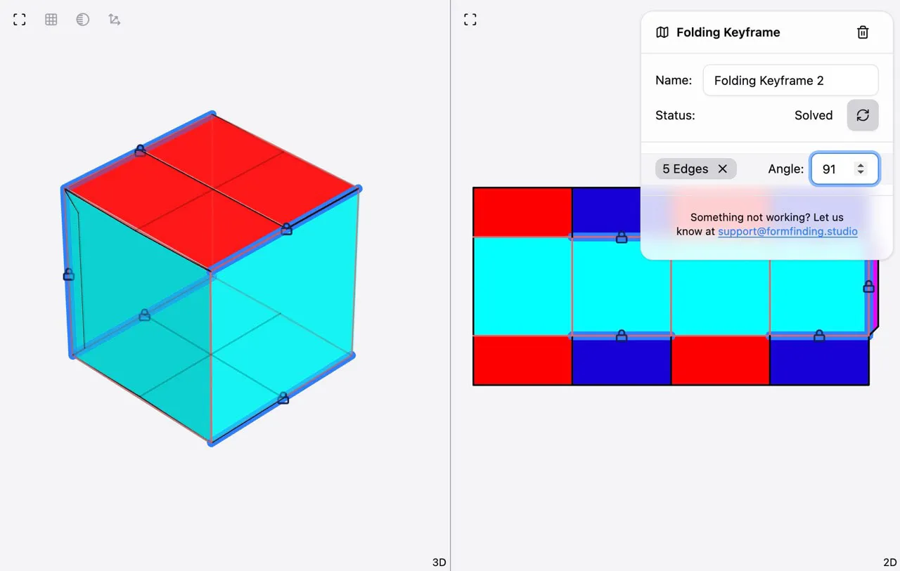
The easiest fix for dealing with overlapping panels is to adjust the fold angles of your design slightly so that the panels no longer intersect in 3D. In the example above, we originally had all the fold angles in the design set to 90°, but if we set a few of the fold angles to 91°, we can fix the overlapping areas without a noticeable difference in the 3D geometry:
See our 3D Folding Simulation guide for details on working with fold angle constraints.
Crease Adjustment
Sometimes a simple angle adjustment, as demonstrated above, is not sufficient to fix the overlap problem. In these cases, we can make some slight adjustments to the creases in the dieline to prevent 3D overlaps.
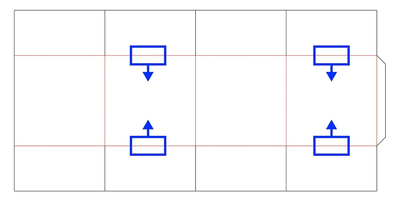
In our example, we want the blue flaps to lie underneath the red flaps when all the flaps are folded to 90°. To achieve this, we need to adjust the creases adjacent to the blue panels in order to vertically offset the panel positions in the folded design. For the blue panels on the top of the box, the creases will shift slightly down; for the blue panels on the bottom of the box, the creases will shift slightly up:
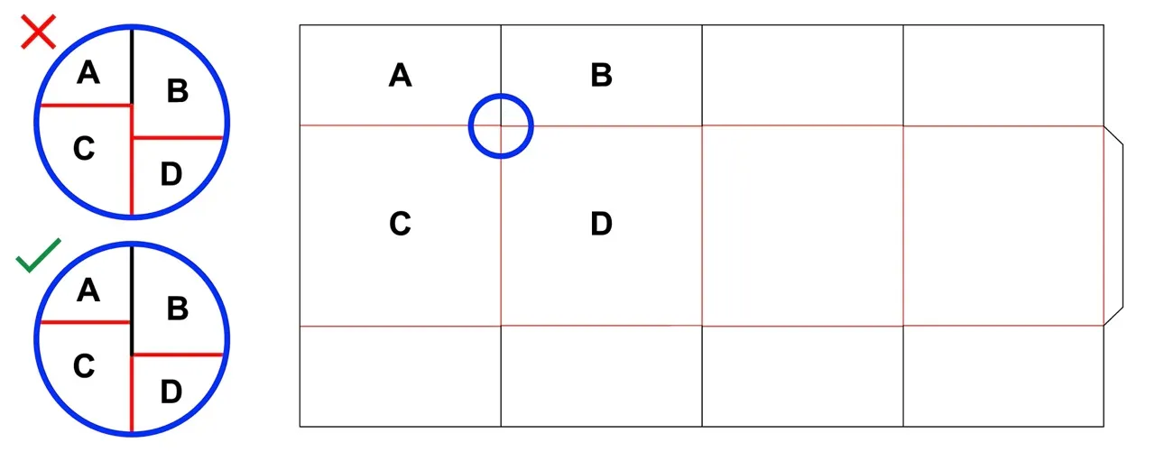
Be sure that the crease adjustment does not introduce any additional crease lines into the dieline. In the example below, the incorrect solution creates a crease between panels B and C, which was not present in the original dieline:
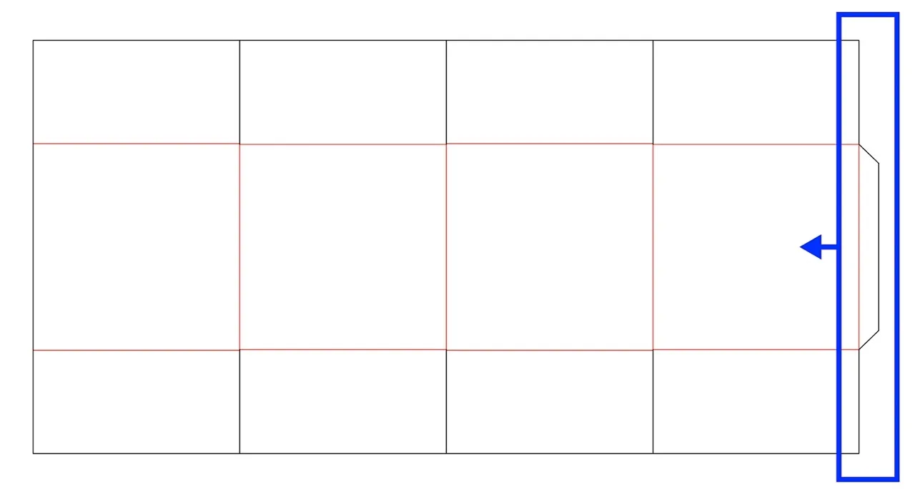
Next, we will move the crease connecting the glue flap slightly to the left so that it positions the glue flap inside the box. The easiest way to achieve this is to shift the entire right edge of the dieline slightly over to the left:
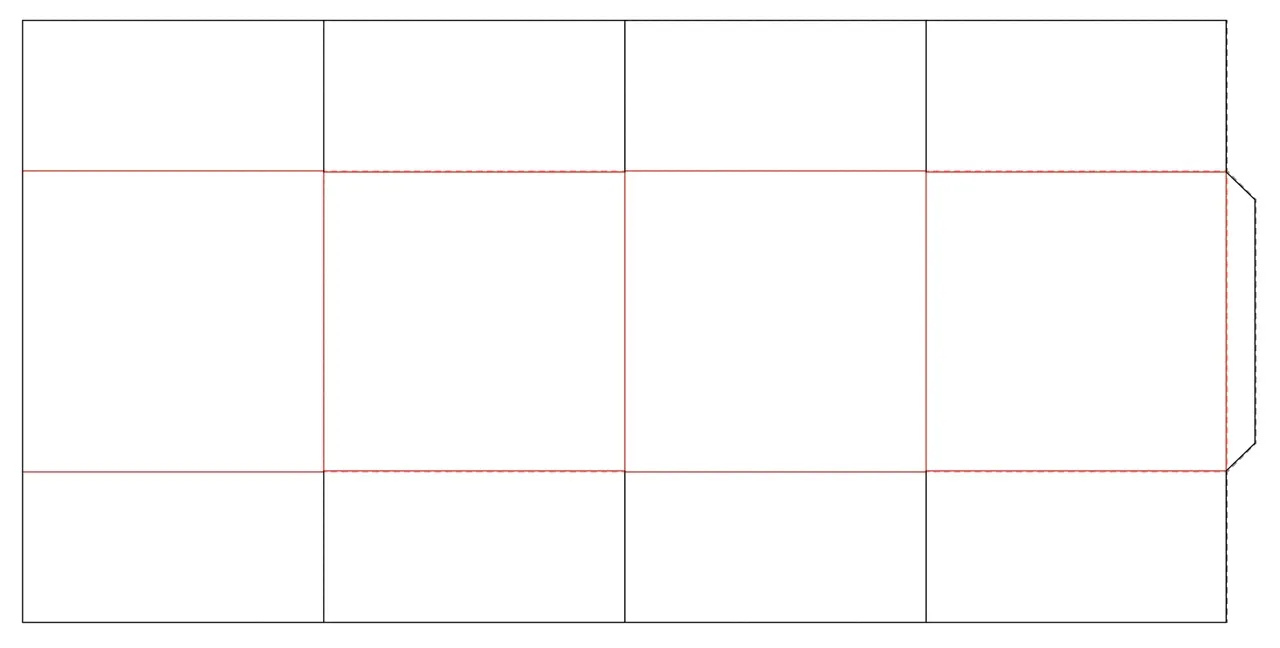
If we adjust these creases by a distance equal to the thickness of the material, then the flaps will not intersect at all in 3D — but even a very small adjustment (much smaller than the thickness of the material) will fix the visual glitch without changing the dieline too much. In this example we are only adjusting the creases by 0.01”, even though the thickness of the material is set to 0.0625”. The difference is very subtle, but you can see the adjusted dieline (solid) overlaid on the original dieline (dashed) in the image below. Download the original and adjusted dielines here: OverlappingFlaps.ai
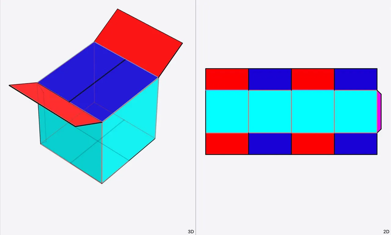
After making these adjustments, the design looks as intended when all creases are folded to 90°. The red flaps are on top of the blue flaps:
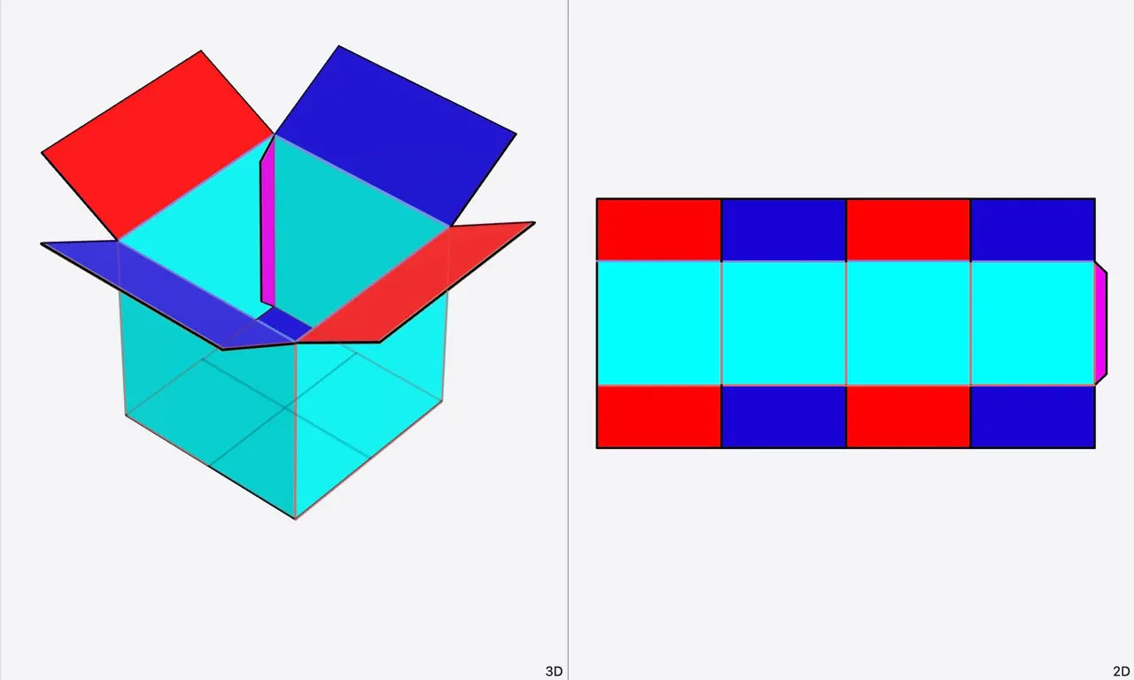
Opening the box slightly reveals the blue flaps underneath:
And the magenta glue tab is only visible from the inside of the box:
Splitting 180° Creases
Next we’ll take a look at 180° folding. Ideally, when a panel is folded completely over, it should be slightly offset from the adjacent panel so that the two panels align face-to-face.
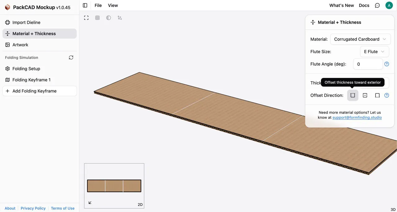
In the Material & Thickness detail menu, you can adjust the thickness Offset Direction to achieve this result. For designs with 180° folding, use (offset thickness toward exterior), and for designs with -180° folding, use (offset thickness toward interior).
Setting the appropriate thickness offset direction will give good results in most cases; however, some designs may not allow this flexibility or may include both 180° and -180° folds within the same dieline. In these cases, you can split 180° creases into two 90° creases to better control how the design folds in 3D.
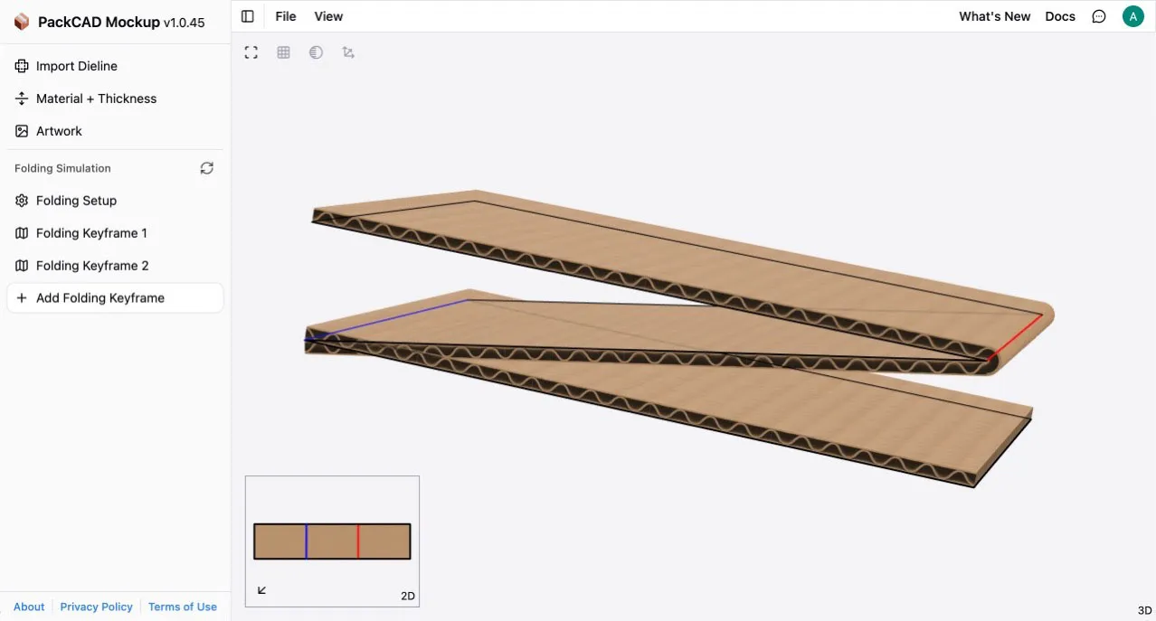
Below we have a simple design that folds into a Z shape using both 180° and -180° folds. We set the thickness Offset Direction to exterior, which works for the 180° fold, but the -180° fold is not behaving correctly in the visualization (partially folded below for clarity):
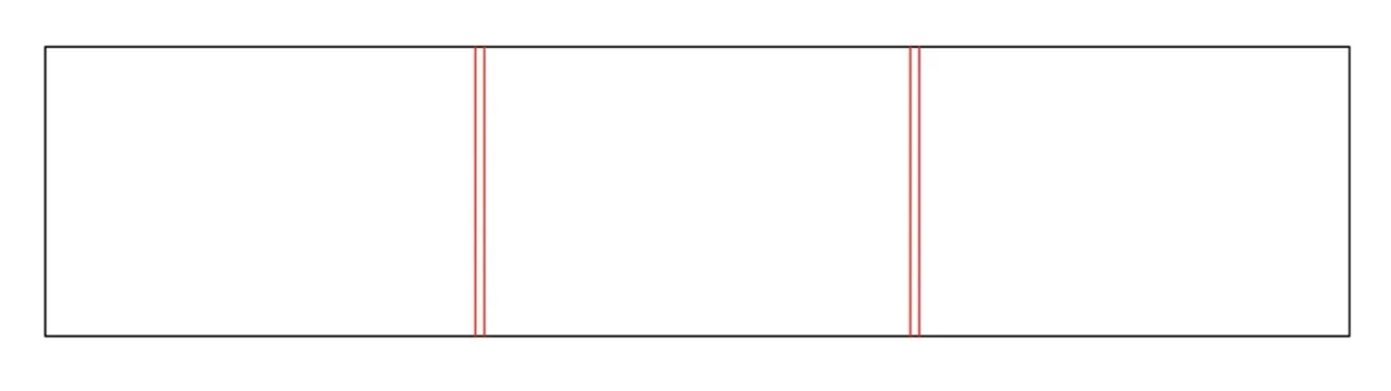
To fix this, replace each +/-180° crease in the dieline with two parallel creases. Our modified design with split creases can be downloaded here: SplitCreases.svg If you want adjacent panels to line up face-to-face when folded, the distance between the split creases should equal the thickness of your material (in this example we are using 0.0625” cardboard):
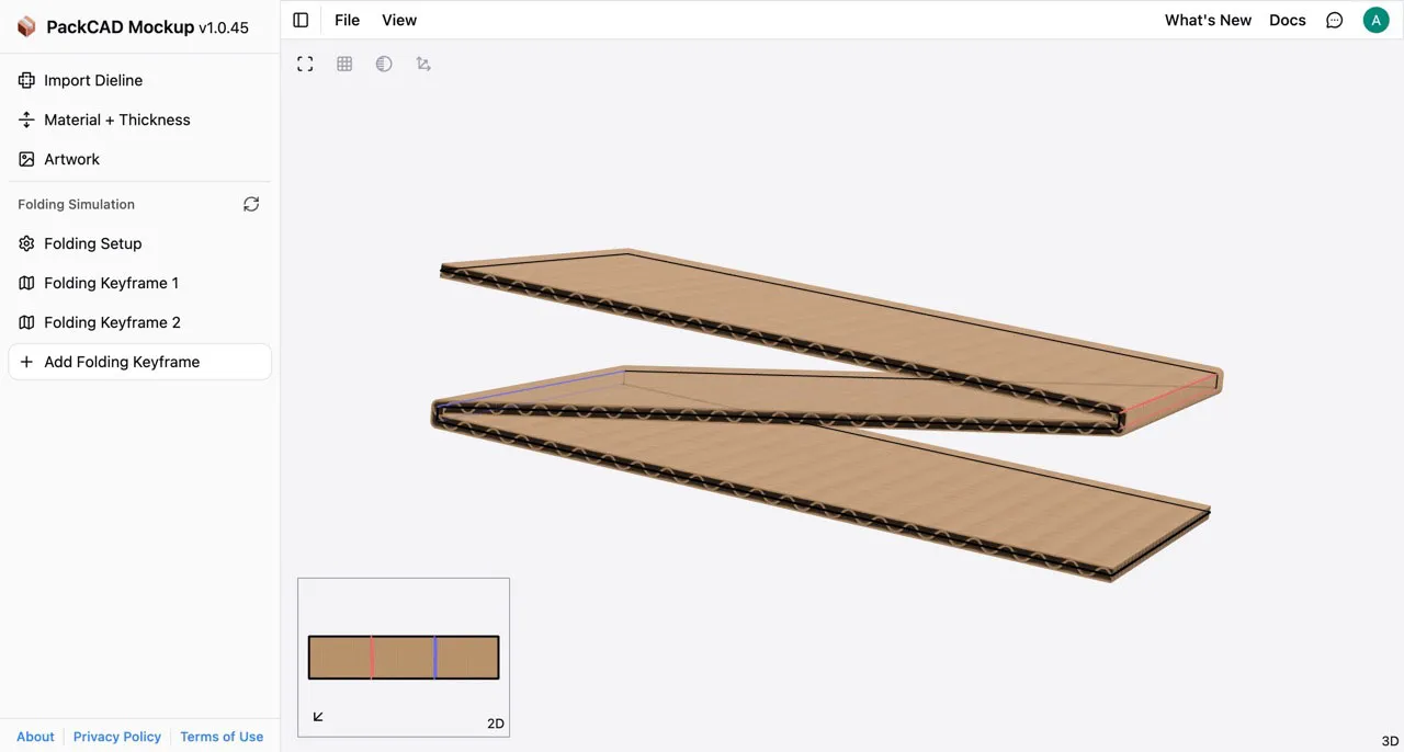
Import the new dieline and set the thickness Offset Direction to (offset thickness on both sides) to get a more symmetric final result. Since we split each +/-180° crease into two creases, the two child creases will only be folded to +/-90°. Here is our final design partially folded:
And fully folded to +/-90° at each of the split creases: